MULTICELL BEAMS
BENDING
When determining the bending stresses, there is no difference if the section is multicell or notbecause for bending only the boom areas are used. So in order to do this calculation just use the
equations derived in Chapter 3.
TORSION
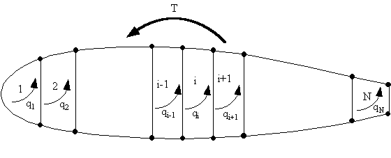
Look at a wing section made of 'N' cells carrying a torque 'T'.
|
Figure 80: Multicell wing structure with applied torque T |

(5.1), which is:
![]()

compatibility relationship.
Effect of Booms on Shear Flow Distribution
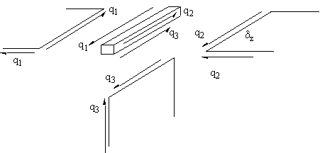
Look at an elemental section of wing of length z, where three skin sections are in contact witha boom of area B, Figure 81.
|
Figure 81: Equilibrium of boom/skin/web junction |
the boom experiences forces only produced by shear flows because no direct stresses are
present. Therefore the booms don't affect the analysis in pure torsion. Summing the forces along boom gives:
![]()
![]()
This equation means that the sum of the shear flows into a junction must equal the sum of the
shear flows out of the junction. This is similar to fluid flow in a multi pipe system. Which is why
we use the term shear flow.
Compatibility Equation for Each Cell
Due to the ribs in aircraft wings, the rate of twist is constant for all cells in the section. So lookat the rate of twist of cell i in the wing section of Figure 80 . Equation (4.21) then becomes for
cell i equal to:

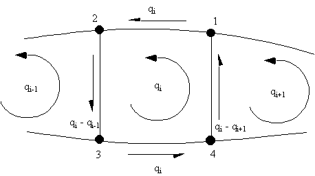
i + 1, and determine the bound integral at cell i of equation (4.21).
|
Figure 82: Shear flow distribution in the ith cell of an 'N' cell wing beam section |

![]()
![]()
becomes:

multiple of its thickness times its shear modulus D i = Sum of all Ds for cell i D ( i + 1 , i ) = length of wall common with the i and i + 1 cell divided by the multiple
of its thickness times its shear modulus With the rate of twist equation for all cells in the structure + the torque equation, you can solve
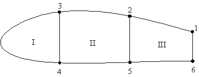
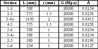
them simultaneously to determine the value of the shear flows in the structure. Example 11: Calculate shear stress distribution in the walls of the 3 cell wing section
subjected to a positive torque of 12000 kNmm
|
|
|
Figure 83: Three cell wing section loaded by a pure torque |
|
Figure 84: Table where D is calculated |
![]()


the following way:


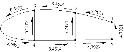
qI = 8.6923 N/mm, qII = 8.4515 N/mm, qIII = 4.7021 N/mm
|
Figure 85: Shear flow distribution in three cell wing section with applied torque |
Note: By dividing the above values of shear flow by the respective wall thickness, gives the
Shear Stresses in the walls in MPa.
SHEAR LOADS
To determine the shear flow distribution in a multicell beam we use the same analysis as for asingle close cell beam.
|
Figure 86: Multicell wing section with applied shear loads |
to determine the shear flow due to an open beam section, then determine the cut skin sections
shear flow, qs,0, add this to the open beam shear flow and determine the true shear flow
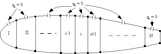
experienced by the section. A multicell wing section can be made statically determinate by cutting a skin panel in each cell.
The best place to cut the cells is always at the centre of the top or bottom skin panels. The reason for this is that when a cell is loaded vertically, the shear flows are zero at these
positions, so that when determining the cut section shear flow its value will be close to zero,
minimising numerical errors. If we do this to our idealised wing section, then that panel's shear flow would be zero. If that
section was symmetrical, the bottom panel will also have a zero open cell shear flow. The
section will look like this:
|
Figure 87: Multicell wing structure loaded by shear loads, indicating the best location for cutting the cell. |
in Chapter 6 and was given by equations (6.12), (6.13) and (6.15).


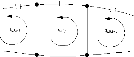
wing section. However there remain N number of unknown values of shear flows at each of the
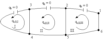
cuts, ie: qs,0,I, qs,0,II, qs,0,III, . . . . , qs,0,N, which are constant for each cell, shown in Figure 88.
|
Figure 88: Redundant shear flow in the ith cell of N cell wing structure loaded in shear |


thus giving:


beam shear flow multiplied by D for all the skin sections surrounding cell i, equation (7.5).


N equations to solve for the unknown qs,0,i's. The extra equation is found by considering the
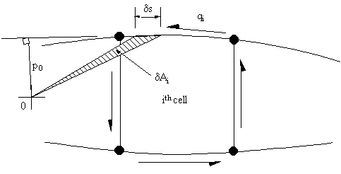
moment equilibrium of all cells. Look at the ith cell, the moment Mq,i produced by the total shear flow about some point '0' is as
follows:
|
Figure 89: Moment equilibrium of ith cell |

![]()

loads so:


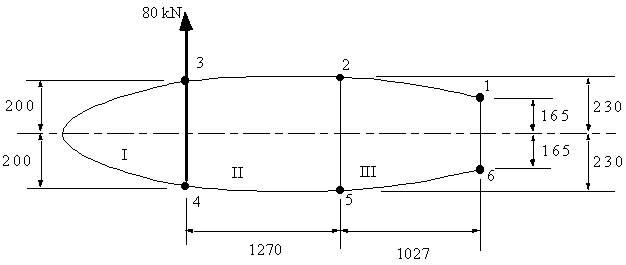
34, determine the shear flow distribution and the rate of twist. Boom areas, B1,6
= 2580 mm2, B2,5 = 3880 mm2, B3,4 = 3250 mm2.
|
Figure 90: Idealised wing section with applied vertical shear load |
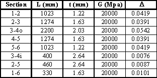
|
Figure 91: Table with calculated D |
|
Figure 92: Three cell wing section cut to determine open beam shear flows |
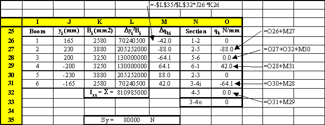
Figure 93.
|
Figure 93: Excel table where the open beam shear flows were calculated |
|
Figure 94: Idealised wing section showing open beam shear flows |

![]()

![]()


![]()
![]()

|
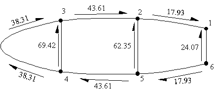
Figure 95: Wing section with final shear flows |
![]()
SHEAR CENTRE
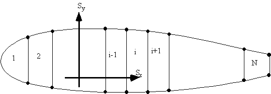
The position of the shear centre is found in an identical manner to that of section 4.5. Arbitraryloads Sy and Sx are applied in turn through the shear centre s.c., the corresponding shear flow
distributions determined and moments taken about some convenient point. The shear flow distributions are found as described in the previous section, except that the N
equations derived using equation (7.4) are enough to determine the unknown shear flows. This
is because the rate of twist of a beam loaded at the shear centre is zero, (
