- Variable Stability Flight Simulator
- 6 Degree of Freedom Load Cell
- Fuel Cell Test Bench
Variable Stability Flight Simulator - Dr. P.W. Gibbens
This document describes the usage of funding from the RW McKenzie Resource Centre budget for 2008.
The funding was used to accelerate the development of a static flight simulator. This simulator is to be used
as an experiential learning laboratory aimed at improving student learning in flight dynamics and control and
aircraft design. The facility will demonstrate the connection between theoretical aerodynamic design
parameters and the consequent handling qualities of a given aircraft. The university has recently placed
great emphasis on teaching and learning infrastructure. Related flight simulation initiatives won the Vice
Chancellor’s Award for Outstanding Teaching (2010) and an Australian Learning and Teaching Council
citation for Outstanding Contributions to Student Learning (2010).
In 2008 the RW McKenzie Centre fund management committee approved funding for PCs and LCD monitors
to equip a new flight simulation facility in the Aeronautical Engineering sector of the School of AMME. This
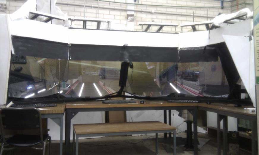
facility makes use of a large 5 segment collimator array recently decommissioned by QANTAS from their
Boeing B747-200 flight simulator. The collimator was donated to SAMME but required fitting with new image
generators and display systems. The Collimator is shown below, set up for integration and testing in the
W & A Bennett Laboratory.
The equipment purchased under the grant included the following
- 2x30” High resolution LCD monitors for the primary forward looking collimator segments
- 2x30” spare High resolution LCD monitors to ensure forward compatibility in case of failure
- 2x25” LCD monitors for left and right diagonal collimator segments
- 1x27” LCD monitor for right-hand lateral collimator segment
- 1x 25” LCD monitor for the Operator station
- 1x22” monitor to upgrade the Operator station display in the existing Variable Stability Flight
Simulator (VSFS)
- 5xPCs with high-end GTX9800 graphics cards to act as image generators to drive the primary
display monitors using xPlane software.
The development of this facility is an ongoing project that will ultimately provide a static ground-based
simulator with more open access than the existing motion-based VSFS. In the meantime, it provides
students with thesis projects involving system integration as they work toward full implementation of the
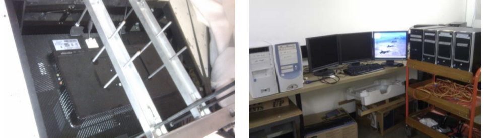
system. As of September 2011 the 5 primary LCD monitors have been installed in the collimators (see figure
below showing a typical monitor installation from above). The PCs (also shown below) have been connected
and visual calibrations of the 5 displays has been achieved. The displays have been successfully used to
simulate aircraft motion and were on display and available for public trial on University Open Day in August 2011
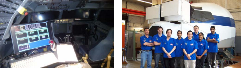
The replacement monitor for upgrade of the Operator Station in the VSFS has been installed and is
operational. This monitor is shown installed in VSFS below.
Overall the project is progressing well. Ongoing work is aimed at developing the remaining cockpit
instrumentation including centre-console and instrument displays, and integration of throttle and joystick
controls. It is expected that the collimator system will be relocated to a more permanent location in the next
12 months and a secure enclosure built. It is hoped that the new facility will be available to undergrad and
postgraduate students to complement the VSFS and aid their studies in Flight Mechanics and Aircraft Design
within the next year or so.
Back to Top
6 DoF Load Cell - Dr. KC. Wong
One of the essential enabling resources for experimentation in Aeronautical Science and Technology
would be the ability to measure multi-axis forces and moments of items being tested in airflow. Six-
component load cells are needed, particularly for testing of models in wind tunnels, to measure the
aerodynamic forces and moments acting on the objects being tested. The Aeronautical Group
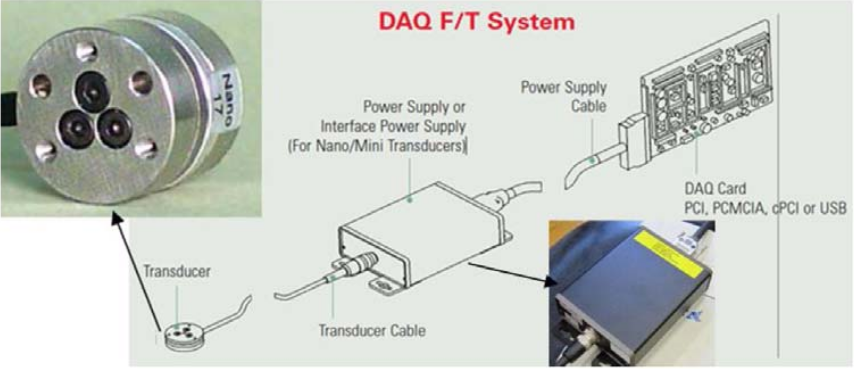
previously acquired an ATI Mini45 Force/Torque sensor system for general wind tunnel experimentation,
so the ATI Nano17 Force/Torque sensor system was selected to provide a complementary capability for
the testing of small models typical of mAVs (mini Air Vehicles) which require the detection of very low
magnitude forces and moments.
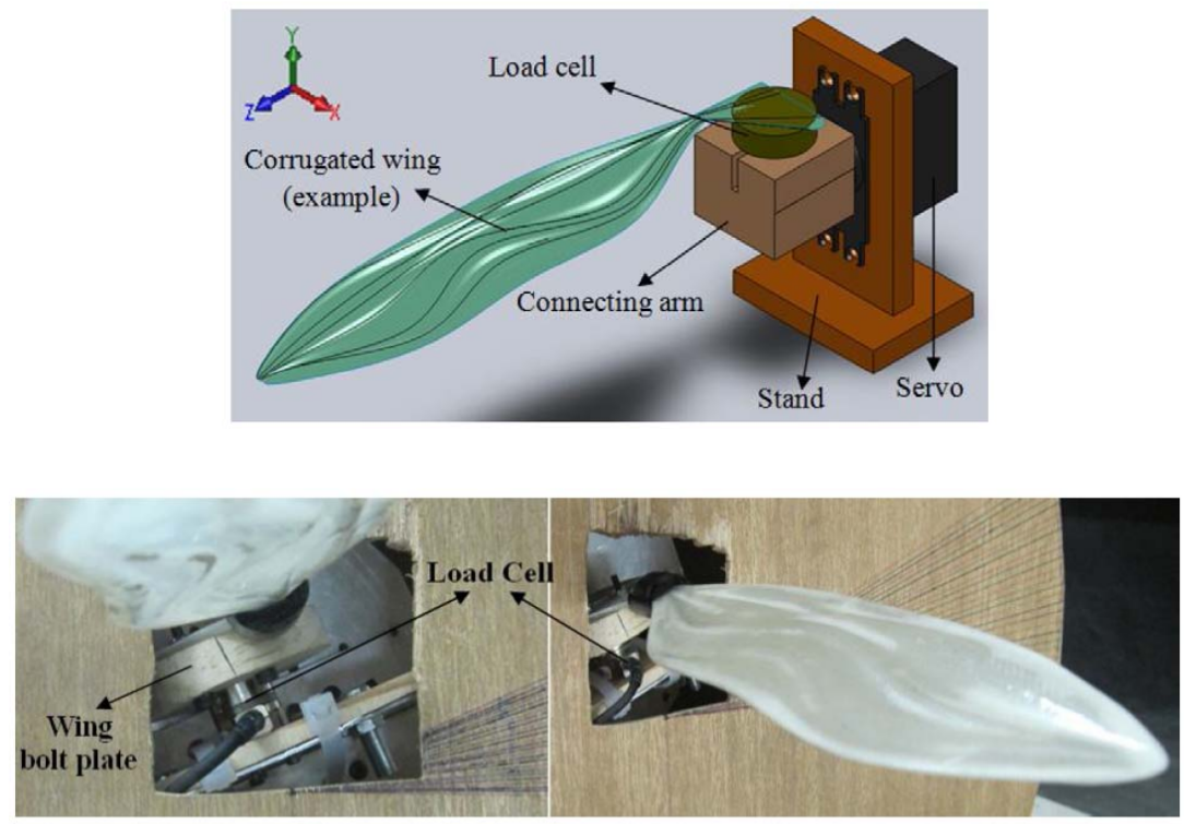
One project which would not have been possible without the availability of this load cell was the
investigation of effect of corrugations on the aerodynamic characteristics of a dragonfly wing in 2010.
Models of wings mimicking the corrugated profile of dragonfly wings were tested against wings with
conventional aerofoil and flat-plate profiles. The small wings were mounted on the Nano17 load cell and
tested in a wind tunnel.
Back to Top
Fuel Cell Test Bench - Dr. Dries Verstraete
Greenhouse gas emissions and their impact on global warming are an increasing concern for the entire
transportation sector. The aviation sector has a stronger than average focus on their environmental impact
and is at the forefront of technology changes. Fuel cells can significantly reduce the emissions of CO2 of
aviation seen their high efficiency compared to conventional propulsion technologies. For unmanned electric
aircraft they furthermore allow a significant increase in flight endurance as shown below.
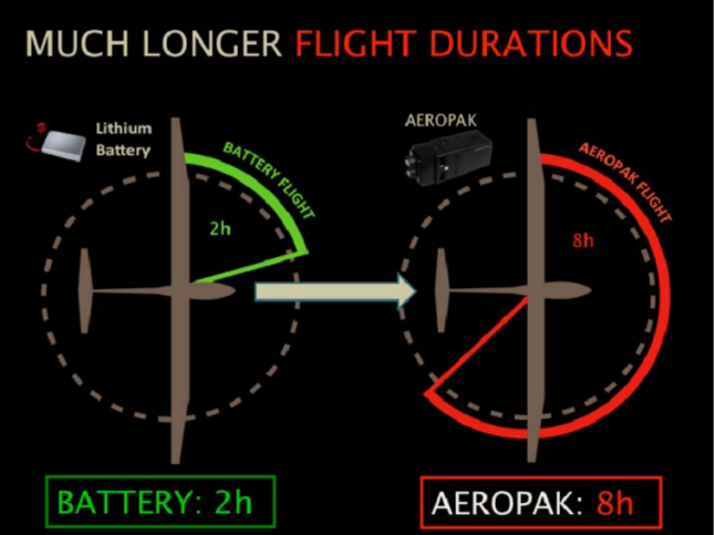
Fuel cell benefit for flight endurance
Through the RW McKenzie Centre funding, the School of Aerospace, Mechanical and Mechatronic
Engineering acquired an electronic load to drive the fuel cell, as shown on the photos below. Without this
funding support, the acquisition of the electronic load would have been impossible and the test bench would
have been far more limited in scope. The Aeropak fuel cell was acquired from a faculty start-up fund for Dries
Verstraete. As such, the funding allowed the School to perform research on this cutting-edge technology and
gain a significant understanding of the challenges associated with the use of this new technology.
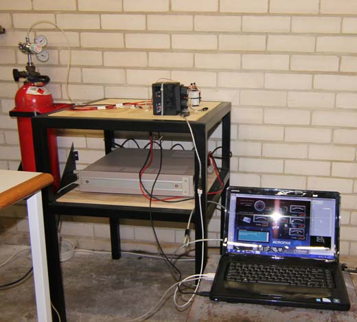
Fuel Cell and load integrated in test bench
As the fuel cell has to be coupled to a brushless DC electrical motor, additional RW McKenzie Centre
funding was put into the acquisition of a precise low power motor testing system. The Land and Sea
dynamometer that was bought is a unique design for precise testing of low power electrical brushless
motors. The dynamometer is shown on the left hand side of the figure below whereas the test stand is
shown on the right hand side.
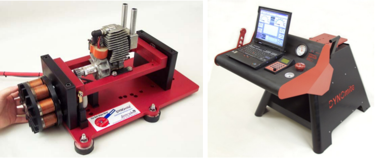
Micro dynamometer and engine test bench
Back to Top