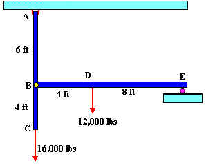
1. In the structure shown below members ABC and BDE are assumed to be solid rigid members. Member BDE is supported by a roller at point E, and is pinned to member ABC at point B. Member ABC is pinned to the wall at point A. Member ABC is a aluminum rod with a diameter of 1 inch. For this structure:
How many reaction forces are in joints A and E.
Draw a Free Body Diagram showing all support forces and loads.
Solution:
External support reaction -
Statics: STEP 1: Draw a free body diagram showing and labeling all load forces and support (reaction) forces, as well as any needed angles and dimensions.
STEP 2: Break any forces not already in x and y direction into their x and y components.
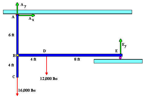
Point A has two reaction forces (or external support reactions), since it is a pin joint. Point E is a roller, so it has just one reaction support perpendicular to the surface it is moving on.