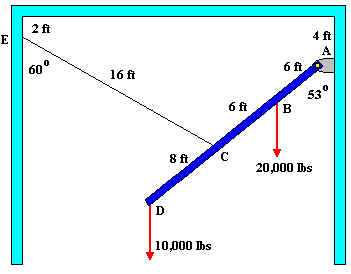
2. In the structure shown below member ABCD a solid rigid member pinned to the wall at A, and supported by steel cable CE. Cable CE is pinned to the wall at E and has a diameter of 1 inch. For this structure:
Draw a Free Body Diagram showing all support forces and loads.
Solution:
External support reaction -
Statics: STEP 1: Draw a free body diagram showing and labeling all load forces and support (reaction) forces, as well as any needed angles and dimensions.
STEP 2: Break any forces not already in x and y direction into their x and y components.
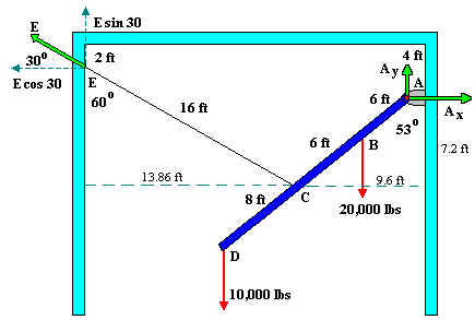
Pin A has two support reaction forces (along x and y). Cable Ce imposes a force on point E along the direction of the cable (force E). Remember that you can always consider two forces along x and y for E, but the angle between force E and its x component should be 30 degrees.