BLUFF-BODY FLOWS AND FLAMES
The bluff-body burner, like the piloted burner, provides a flame suitable for the study of turbulence-chemistry interactions. Bluff-body burners also bear a great similarity to practical combustors used in many industrial applications. This geometry is, therefore, a suitable compromise as a model problem because it has some of the complications associated with practical combustors while preserving relatively simple and well-defined boundary conditions.
The burner is centred in a coflowing stream of air and generally consists of a circular bluff-body with an orifice at its centre for the main fuel. A complex flow pattern forms downstream of the face of the bluff-body where a recirculation zone is formed to produce enough hot gases to stabilise the flame to the burner. At sufficiently high fuel velocity, the jet flow penetrates through the recirculation zone and forms a jet-like flame further downstream, which is not unlike the piloted jet flame. The jet flame can be extinguished in a region downstream of the recirculation zone where turbulence is well developed and the finite rate chemistry effects are significant. The flame may also reignite further downstream where turbulent mixing rates are relaxed. It should therefore be noted that both the piloted and the bluff-body jet flames discussed here consist, generally, of three main zones: stabilisation, extinction and re-ignition zones.
Bluff-body
burners have been used with a range of bluff-body diameters, Db and
fuel jet diameters, Dj. Stability characteristics of these flames are
given in terms of the fuel jet velocity, uj and the coflow velocity,
ue; and have been published elsewhere [1,10]. The length of the
recirculation zone is about one bluff body diameter. It should be noted here
that the addition of H2 or CO to the CH4 fuel is intended
to produce a recirculation zone which is clean from soot. In pure CH4
flames [8] the recirculation zone, generally, has soot or soot precursors which
are convected downstream where they interfere with the Raman signals. Partially
premixing the methane with air reduces the flame's tendency to soot and this may
lead to a much cleaner recirculation zone. Methanol fuel is extremely useful in
this regard since it produces a clean recirculation zone without the need of
premixing with another fuel.
Ue - External ambient coflow velocity. Significant in effecting mixing downstream of the neck region. Higher velocities leads to higher gas momentum around the burner and bluff-body, leading to more significant 'pinching' at the neck. The free stream turbulence in the coflow is around 2%.
Uj - Fuel jet velocity. The bulk average jet velocity through the central fuel tube. Higher velocities leads to higher fuel jet momentum.
Dj - Fuel jet diameter. Simply the inner diameter of the central fuel jet. Typically, this value is constant at 3.6mm but data sets exist for smaller diameters on the departmental server.
Db - Bluff-body diameter. The outer diameter of the ceramic bluff-body face (Db = 50mm, for this burner).
|
|
|
|
Burner Schematic |
Flame Image |
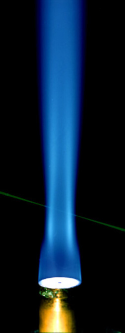
Click on either image for a larger view.
LDV technique is used to measure simultaneously the axial and radial velocity components. Two colour beam of 5W, Argon-Ion laser is used. The beam fringes for the two colours have a 10Mhz frequency in the positive direction to eliminate ambiguity. Two Photomultiplier Tubes (PMT) with colour filters are used to collect the forward scatter from the two beams. The output signal is filtered and passed through two 1D TSI frequency counters.
Measurements of mixture fraction in Non-reacting Bluff-Body jets are performed using planar imaging of Rayleigh scattering. These imaging experiments were performed at the University of Sydney. The instantaneous images have a dimension of 58x13x0.5 mm which covered the full width of the bluff-body flow.
Three sets of 50 images were collected in the vicinity of the recirculation zone. The images were corrected for electronic and photon noise, background interferences and stripeness caused by the change of refractive indices which induce beam steering. The mixture fraction is estimated to have errors associated with electronic and photon noise of less than 5.7% and at best this error drops to 2.3%. These estimates do not account for any systematic errors that may be associated with these measurements.
The
results presented are in the form of mean and rms mixture fractions
obtained at various locations within the imaged planes.
INITIAL & BOUNDARY CONDITIONS:
The initial conditions (at the jet exit plane) and boundary conditions (in the coflowing stream) are described here. The mean mixture fraction, the mean velocities and the variances and covariances for the velocities are specified. The mean mixture fraction is taken to be one in the jet stream and zero in the air stream. Mixture fraction in the pilot stream is generally taken as stoichiometric unless otherwise specified. The measured initial conditions for the mean axial velocity, u and its rms fluctuations u' normalised with the mean velocity are tabulated.
Initial
Conditions for:
Bluff-Body Stabilised Jets and Flames file: icbbody.dat
Modellers
may chose to use the actual measured initial conditions as specified in the
tables. This will ensure that the jet initial velocity and momentum are
accounted for. Initial radial and circumferential velocities are taken as zero,
v = w = 0. It is also assumed that the initial profiles of v' and w' are
identical to those of u'. The initial covariances have not been measured but may
be taken as:
![]()
where C_cv is a constant equal to 0.5. All other covariances are zero.
An alternative to using the tabulated initial conditions is to use power law fits for the initial velocity profiles both in the jet (approximating fully developed turbulent pipe flow) and the coflow. Initial profiles for u' are specified as piece-wise linear. Sharp changes in velocity may be intentionally avoided for computational purposes. Although these specified velocities may deviate slightly from the measured ones, the momentum both in the jet and the coflow streams are within 2% of the momentum at the specified conditions. The net momentum deficit in the coflow stream due to the boundary layer is accounted for in the computations.
Both u and u' are taken as zero on the bluff-body surface.
The coflow air boundaries should be set wide enough to include the full boundary layer on the coflow side and to ensure that the boundary specifications do not influence the jet. The pressure gradient at the coflow boundaries is taken as zero. Constant pressure could also be applied at the exit plane. The face of the bluff-body burner is covered with ceramic and turns red hot especially when a full, visible flame exists in the recirculation zone. Heat losses to the bluff-body burner should, therefore, be accounted for. It is good practice to extend the grid upstream of the nozzle exit to ensure that fully developed pipe flow conditions prevail at the nozzle exit plane.
A detailed description of the sources of error on the single-point Raman and Rayleigh is given in Readme-fst.txt.
Typical signal to noise ratios (S/N) are given in the following files:
S/N
ratios for data collected 1992 and before stn92.dat
S/N ratios for data collected 1995 and after stn95.dat
Flow Field Data:
Mean and rms fluctuations of axial and radial velocities:
| Burner Description | Fuel Mixture | Data File |
| Bluff-Body(50mm body, 3.6mm jet) |
Air |
b4c1-s1.dat |
| Same case, Data set 2 | b4c1-s2.dat | |
| Same case, Data set 3 | b4c1-s3.dat |
Mixing Field Data
Obtained from Rayleigh Imaging. Mean and rms fluctuations of mixture fraction:
| Burner Description | Fuel Mixture | Link |
| Bluff-Body(50mm body, 3.6mm jet) | Ethylene (C2H4) | B4C1 |
| Bluff-Body(50mm body, 3.6mm jet) | CNG (CH4) | B4C2 |
| Bluff-Body(50mm body, 3.6mm jet) | LPG (C3H8) | B4C3 |
Flow Field Data:
Mean and rms fluctuations of axial and radial velocities:
| Burner Description | Fuel Mixture | Data File |
| Bluff-Body(50mm body, 3.6mm jet) | CNG/H2(1/1) | |
| Flame
HM1: U-Fuel=118m/s, U-air=40m/s, 50% blowoff |
b4f3-a-s1.dat | |
| Flame
HM1E (set 1): U-Fuel=108m/s, U-air=35m/s, 50% blowoff |
b4f3-b-s1.dat | |
| Flame
HM1E (set 2): Data set 2 |
b4f3-b-s2.dat | |
| Flame
HM3E: U-Fuel=195m/s, U-air=35m/s, 90% blowoff |
b4f3-c-s1.dat |
Temperature of Ceramic Bluff-Body Face (word doc)
NOTE: Flame HM1E is the equivalent flame to HM1. The wind tunnel at Sydney Uni was unable to generate a uniform 40m/s coflow. (Maximum was 35m/s). The jet velocity was accordingly reduced (from 118m/s to 108m/s) so that both HM1 and HM1E are at the same proportion from blow-off.
NOTE: For the velocity information in the reacting flames, CNG is used in place of methane. CNG is 90% methane, with the remaining fraction made up of butane and other hydrcarbons. Flame speed and stability limits vary only slightly between the two fuels. The Compositional measurements are conducted using pure CH4, not CNG.
Spontaneous Raman/Rayleigh/LIF Data:
Temperature and species mass fractions
| B-Body (mm) |
Jet (mm) |
Fuel mixture |
Link | Year
of Expt. |
| 38 | 2 | CH4 | b1f1 | 1992 |
| 38 | 2 | CH4/H2(2/1) | b1f2 | 1992 |
| 50 | 2 | CH4 | b2f1 | 1992 |
| 50 | 2 | CH4/H2(2/1) | b2f2 | 1992 |
| 50 | 2 | CH4/CO(1/1) | b2f3 | 1992 |
| 60 | 4.6 | CH3OH | b3f1 | 1989 |
| 50 | 3.6 | CH3OH | b4f1 | 1995 |
| 50 | 3.6 | H2/CO(2/1) | b4f2 | 1995 |
| 50 | 3.6 | CH4/H2(1/1) | b4f3 | 1995 |
Conditional and Radial Means & RMS Data:
| B-Body (mm) |
Jet (mm) |
Fuel mixture |
File | Year
of Expt. |
| 38 | 2 | CH4 | b1f1 CM | 1992 |
| 38 | 2 | CH4/H2(2/1) | b1f2 CM | 1992 |
| 50 | 2 | CH4 | b2f1 CM | 1992 |
| 50 | 2 | CH4/H2(2/1) | b2f2 CM | 1992 |
| 50 | 2 | CH4/CO(1/1) | b2f3 CM | 1992 |
| 60 | 4.6 | CH3OH | b3f1 CM | 1989 |
| 50 | 3.6 | CH3OH | b4f1 CM | 1995 |
| 50 | 3.6 | H2/CO(2/1) | b4f2 CM | 1995 |
| 50 | 3.6 | CH4/H2(1/1) | b4f3 CM | 1995 |
-
Masri, A.R. and Bilger, R.W., `Turbulent Diffusion Flames of Hydrocarbon Fuels Stabilised on a Bluff Body', Twentieth Symposium (International) on Combustion. The Combustion Institute, Pittsburgh, 1985, pp. 319-326.
-
Dibble, R.W., Masri, A.R. and Bilger, R.W., `The Spontaneous Raman Scattering Technique Applied to Nonpremixed Flames of Methane', Combust. Flame 67:189-206 (1987).
-
Masri, A.R. and Bilger, R.W., `Turbulent Nonpremixed Flames of Hydrocarbon Fuels Near Extinction: Mean Structure from Probe Measurements', Twenty-first Symposium (International) on Combustion, The Combustion Institute, Pittsburgh, 1988, pp. 1511-5120.
-
Masri, A.R., Dibble, R.W. and Bilger, R.W., `Turbulent Nonpremixed Flames of Methane Near Extinction: Mean Structure from Raman Measurements', Combust. Flame 71:245-266 (1988).
-
Masri, A.R., Bilger, R.W. and Dibble, R.W., `Turbulent Nonpremixed Flames of Methane Near Extinction: Probability Density Functions', Combust. Flame 73:261-285 (1988).
-
Masri, A.R., Bilger, R.W. and Dibble, R.W., `Conditional Probability Density Functions Measured in Turbulent Nonpremixed Flames of Methane Near Extinction', Combust. Flame 74:267-284 (1988).
-
Masri, A.R., Bilger, R.W. and Dibble, R.W., `The Local Structure of Turbulent Nonpremixed Flames Near Extinction', Combust. Flame 81:260-276 (1990).
-
Masri, A.R., Dibble, R.W. and Barlow, R.S., `The Structure of Turbulent Nonpremixed Flames of Methanol over a Range of Mixing Rates', Combust. Flame 89:167-185 (1992).
-
Masri, A.R., Dibble, R.W. and Barlow, R.S., `Chemical Kinetic Effects in Nonpremixed Flames of $H_{2}/CO_{2}$ Fuel', Combust. Flame 91:285-309 (1992).
-
Masri, A.R., Dibble, R.W. and Barlow, R.S., `Raman-Rayleigh Measurements in Bluff Body Stabilised Flames of Hydrocarbon Fuels', Twenty-fourth Symposium (International) on Combustion, The Combustion Institute, Pittsburgh, 1992, pp. 317-324.
-
Masri, A.R., Dally, B.B., Barlow, R.S. and Carter, C.D., `The Structure of The Recirculation Zone of a Bluff-Body Combustor', Twenty-fifth Symposium (International) on Combustion, The Combustion Institute, Pittsburgh, 1994, pp.1301-1308.
-
Masri, A.R., Dibble, R.W., and Barlow, R.S., `The Structure of Turbulent Nonpremixed Flames Revealed by Raman-Rayleigh-LIF Measurements', Prog. Energy Combust. Sci., 22:307-362 (1997).
-
Dally, B.B, Masri, A.R., Barlow, R.S., Fiechtner, G.J., and Fletcher, D.F., `Measurements of NO in Turbulent Nonpremixed Flames Stabilised on a Bluff-Body', Twenty-sixth Symposium (International) on Combustion, The Combustion Institute, Pittsburgh, 1996, Vol. 2, pp.2191-2197.
-
Dally, B.B, Masri, A.R., Barlow, R.S., Fiechtner, G.J., and Fletcher, D.F., 'Instantaneous and Mean Compositional Structure of Bluff-Body Stabilised Nonpremixed Flames', Combust. Flame 114:119-148 (1998).
-
Dally, B.B, D.F. Fletcher, and Masri, A.R., 'Flow and Mixing Fields of Turbulent Bluff-Body Jets and Flames', Combustion Theory and Modeling 2:193-219 (1998).
DISCLAIMER: No responsibility is assumed by the suppliers of this data for any injury and/or property damage as a matter of products liability, negligence or otherwise, or from any use or operation of any methods, products, instructions, or ideas based on these data.
© 2002-2018 The University of Sydney.
Last updated: 12 Febuary, 2018
ABN: 15 211 513 464. CRICOS number: 00026A. Phone: +61 2 9351 2222.
Contact the University | Disclaimer | Privacy | Accessibility