SWIRL FLOWS AND FLAMES DATABASE
The swirl burner described here is a simple extension of the bluff-body burner which has been adopted as a model problem for the TNF Workshop Series. It offers simple design with well-defined boundary conditions, yet it produces complex swirling flows which are not unlike those found in practical combustors. An extensive and comprehensive data bank now exists for selected flows in this burner configuration which is now posed as a new challenge for the TNF workshops. A number of papers have already been published or submitted for consideration for publications in various journals.
The swirl burner is centrally located in a air co-flow. The co-flow has around 2% free stream turbulence. The co-flow is either 305mm square (Sandia CRF) or 130mm square (Sydney).
The swirling annulus is air (only). Air for the annulus is supplied through the primary inlet, and/or the tangential injectors.
Fuel issues from the central jet, located in the centre of the ceramic bluff-body face. The jet is fully-developed at the exit plane.
|
|
|
|
Burner Plan |
Burner Schematic |
Velocity measurements were conducted by Yasir Al-Abdeli at the Laser Diagnostics Laboratory at the School of Aerospace, Mechanical and Mechatronic Engineering, Univeristy of Sydney, NSW, Australia.
> Velocity Profiles at Burner boundary Layer (Adobe PDF 80k)
Compositional measurements were conducted, by Dr Rob Barlow and Dr Peter Kalt, at the Turbulent Diffusion Flame (TDF) Laboratory at the Combustion Research Facility, Sandia National Laboratories, Livermore, CA, USA.
Ue , The external ambient coflow velocity. Significant in effecting mixing downstream of the neck region. Higher velocities leads to higher gas momentum around the burner and bluff-body, leading to more significant 'pinching' at the neck. The free stream turbulence in the coflow is around 2%. The external coflow does not swirl.
Us , The axial annular velocity. This is the mean axial component of velocity at the exit plane, emerging from the annular swirling shroud. Primarily responsible for the formation of the primary recirculation zone that stabilises on the face of the bluff-body. Flow through the annulus is fully-developed. Us is the bulk average axial velocity. This parameter is predominantly controlled by the Primary Axial Air flowrate, although the Tangential Air flowrate also has a small effect.
Ws , The tangential annular velocity. This is the mean tangential component of velocity at the exit plane, emerging from the annular swirling shroud. Responsible for generating swirl and subsequent out-of-plane shear-stresses in the flow. Flow through the annulus is fully-developed. Ws is the bulk average tangential velocity. This parameter is controlled by the Tangential Axial Air flowrate.
Uj , The fuel jet velocity. The bulk average jet velocity through the 3.6mm diameter central fuel tube. Higher velocities leads to higher fuel jet momentum. The fuel jet does not swirl.
S , The Swirl Number. The swirl number is an indication of the intensitiy of Swirl in the annular flow. Usually defined as the ratio of tangential to axial momenta, the value quoted here is the geometric swirl number, defined as the ratio of bulk tangential velocity and bulk axial velocity in the annular shroud. (ie S =Ws/Us).
The naming of swirling non-reacting jets on this burner follows a naming convention:
N{XX}S{YYY}.dat where XX is the integer component of the axial annular velocity, Us.
and YYY is the swirl number, S , expressed without the decimal point.The following cases are available for download in non-reacting swirling jets:
N29S054 - Low Swirl Flow
Jet: Air @ 66m/s
Swirl Number: 0.54
Boundary Conditions
Flowfield Measurements (3-component LDV, U V W)
Time Series______________________________________________
N16S159 - High Swirl Flow
Jet: Air @ 66m/s
Swirl Number: 1.59
Boundary Conditions
Flowfield Measurements (3-component LDV, U V W)
Time Series
> Summary of Flowrates to Swirl Burner for non-reacting jets (Adobe PDF 64k)
NOTE: Measurements of boundary conditions are limited by optical access considerations. It is not possible to resolve velocities nearer than 6.8mm to the burner exit plane. These results need to be taken as a close approximation to the exit plane boundary condition (x=0mm).
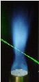
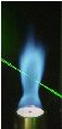
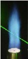
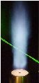
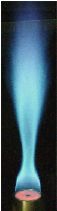
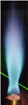
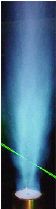
Charateristics of Swirling Flames:
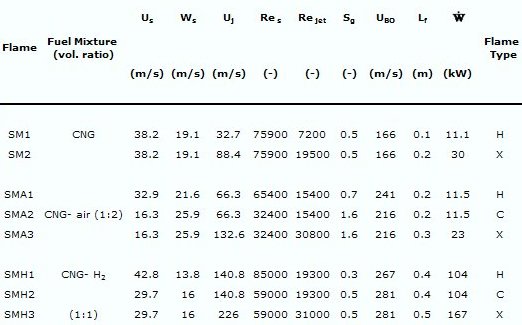
UBO
is the blowoff limit and
Lf
is the visible flame length. LHV
of fuels: CH4=50016 kJ/kg, CH4-air=16672 kJ/kg, CH4-H2=193457
kJ/kg. Heat
release,
![]() ,
is calculated for
stoichiometric combustion and CNG is treated as pure CH4.
,
is calculated for
stoichiometric combustion and CNG is treated as pure CH4.
See
following images for reference to flame type
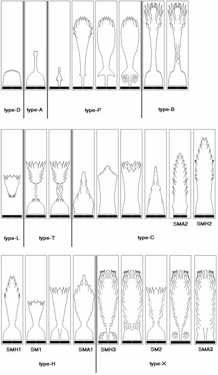
Swirling Flame Data:
The following cases are available for download in non-reacting swirling jets:
SM1 - Swirling Methane Flame
Jet: Methane @ 32.7m/s
Swirl Number: 0.5
Boundary Conditions
Flowfield Measurements (2-component LDV, U & W)
Time Series
Instantaneous Raman/Rayleigh/LIF Data
Conditional and Radial Means & RMS Data______________________________________
SM2 - Swirling Methane Flame
Jet: Methane @ 88.4m/s
Swirl Number: 0.5
Boundary Conditions
Flowfield Measurements (2-component LDV, U & W)
Time Series
Instantaneous Raman/Rayleigh/LIF Data
Conditional and Radial Means & RMS Data______________________________________
SMA1 - Swirling Methane/Air Flame
Jet: Methane/Air (1:2) @ 66.3m/s
Swirl Number: 0.66
Boundary Conditions
Flowfield Measurements (2-component LDV, U & W)
Time Series
Instantaneous Raman/Rayleigh/LIF Data
Conditional and Radial Means & RMS Data______________________________________
SMA2 - Swirling Methane/Air Flame
Jet: Methane/Air (1:2) @ 66.3m/s
Swirl Number: 1.59
Boundary Conditions
Flowfield Measurements (3-component LDV, U V W)
Time Series
Instantaneous Raman/Rayleigh/LIF Data
Conditional and Radial Means & RMS Data______________________________________
SMA3 - Swirling Methane/Air Flame
Jet: Methane/Air (1:2) @ 132.6m/s
Swirl Number: 1.59
Boundary Conditions
Flowfield Measurements (2-component LDV, U & W)
Time Series
Instantaneous Raman/Rayleigh/LIF Data
Conditional and Radial Means & RMS Data______________________________________
SMH1 - Swirling Methane/Hydrogen Flame
Jet: Methane/Hydrogen (1:1) @ 140.8m/s
Swirl Number: 0.32
Boundary Conditions
Flowfield Measurements (2-component LDV, U & W)
Time Series
Instantaneous Raman/Rayleigh/LIF Data
Conditional and Radial Means & RMS Data______________________________________
SMH2 - Swirling Methane/Hydrogen Flame
Jet: Methane/Hydrogen (1:1) @ 140.8m/s
Swirl Number: 0.54
Boundary Conditions
Flowfield Measurements (3-component LDV, U V W)
Time Series
Instantaneous Raman/Rayleigh/LIF Data
Conditional and Radial Means & RMS Data______________________________________
SMH3 - Swirling Methane/Hydrogen Flame
Jet: Methane/Hydrogen (1:1) @ 226m/s
Swirl Number: 0.54
Boundary Conditions
Flowfield Measurements (2-component LDV, U & W)
Time Series
Instantaneous Raman/Rayleigh/LIF Data
Conditional and Radial Means & RMS Data
NOTES: 1) For the velocity information in the reacting flames, CNG is used in place of methane. CNG is 90% methane, with the remaining fraction made up of butane and other hydrocarbons. Flame speed and stability limits vary only slightly between the two fuels. The Compositional measurements are conducted using pure CH4, not CNG.
2) Measurements of boundary conditions are limited by optical access considerations. It is not possible to resolve velocities nearer than 6.8mm to the burner exit plane. These results need to be taken as a close approximation to the exit plane boundary condition (x=0mm).
3) Velocity profiles and Composition profiles may not overlap. Specifically for profiles in the SMH1 flame through the primary recirculation zone.
> Recommended path for the order of calculations of swirling flames (Word Doc94k)
- Kalt, P.A.M., Al-Abdeli, Y.M., Masri, A.R., and Barlow, R.S., 'Swirling Turbulent Non-premixed Flames of Methane: Flowfield and Compositional Structure', Proc. Combust. Inst. 29:1913-1919 (2002).
- Al-Abdeli, Y.M., and Masri, A.R., 'Recirculation and Flow Field Regimes of Unconfined Non-Reacting Swirling Flows', Experimental Thermal and Fluid Sciences, 27(5):655-665 (2003).
- Al-Abdeli, Y.M., and Masri, A.R., 'Stability Characteristics and Flow Fields of Turbulent Swirling Jet Flows', Combust. Theory and Modeling, 7:731-766 (2003).
- Masri,
A.R., Kalt, P.A.M., and Barlow, R.S., 'The Compositional Structure of
Swirl-Stabilised Turbulent Non-premixed Flames’, Combust. Flame, 137:1-37
(2004).
- Al-Abdeli,
Y.M., and Masri, A.R., ‘Precession and Recirculation in Turbulent Swirling
Isothermal Jets’,
Combust. Sci. Technol. 176:645-665
(2004).
This work is supported by the Australian Research Council and the US Department of Energy, Office of Basic Energy Sciences.
Reacting and Non-reacting Velocity fields were resolved using Laser Doppler Velocimetry (LDV) by Mr Yasir Al-Abdeli.
Composition measurements were conducted in swirl flames by Dr Peter Kalt and Dr Rob Barlow.
DISCLAIMER: No responsibility is assumed by the suppliers of this data for any injury and/or property damage as a matter of products liability, negligence or otherwise, or from any use or operation of any methods, products, instructions, or ideas based on these data.
© 2002-2018 The University of Sydney.
Last updated: 12 Febuary, 2026
ABN: 15 211 513 464. CRICOS number: 00026A. Phone: +61 2 9351 2222.
Contact the University | Disclaimer | Privacy | Accessibility