PREMIXED FLAME PROPAGATION
An
ongoing research program at the University of Sydney has been developed to
investigate the important issue of
transient premixed flame propagation and the influence of turbulence and solid
obstacles on the burning rate. In earlier studies [1-2], a large, unconfined
experimental chamber with a volume of about 20 litres was used to study premixed
flames propagating past one turbulence generator and a solid obstacle. This
configuration posed two main problems: (i) the turbulence generated was not
sufficiently high and (ii) the Large Eddy Simulations (LES) being conducted in
parallel with the experiments were extremely time-consuming.
To overcome these problems, a smaller chamber with a volume of less than 1 litre has been designed allowing for (i) the use of multiple turbulence-generating grids without running the risk of deflagration to detonation transition; (ii) broad optical access; and, (iii) a huge reduction in the time needed for sensible LES. The design and construction of the vessel are given on this page along with some early experimental results using a range of configurations for an obstacle and one, two or three turbulence generating grids. Fast video images as well as pressure-time traces show the contorted flame structure and the subsequent effect on overpressure.
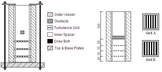
The vessel is square in cross-section, with internal dimensions of 50 x 50 mm, and an overall length of 250 mm. The walls are constructed in two sections: an inner assembly comprised of several 5 mm thick bonded Perspex spacers of varying lengths used to separate a variety grids and obstacles that realise the geometrical configuration for a given experiment, and an outer a box constructed from 20 mm thick Perspex that encapsulates the entire inner assembly for added strength. The inner and outer assemblies are placed between a Perspex base plate and an aluminium top plate, and the entire rig is then held firmly together using draw bolts and mounted on a traverse rig (refer to Figure below).
The turbulence generating grids are constructed from aluminium and placed between the Perspex spacers perpendicular to the propagating flame front. For the preliminary investigations shown on these pages, grids have been situated at any one of three ‘stations’ 20 mm (S1), 50 mm (S2) and 80 mm (S3) downstream of the ignition point. Two separate geometries for the turbulence-generating grid have been used. Grid A consists of five 4 mm wide strips evenly separated by six 5mm wide spaces, whilst Grid B is the inverse of Grid A consisting of six 5 mm wide strips evenly separated by five 4 mm wide spaces (blockage ratios of 0.4 and 0.6 respectively). A square obstruction constructed from aluminium and running the full width of the chamber is also present, having cross-sectional dimensions of 12 x 12 mm and placed parallel to the grids, 100 mm downstream of the ignition point.
|
|
Liquefied Petroleum Gas (88% C3H8, 10% C3H6 and 2% C4H10 by vol.) enters through a non-return valve in the base plate at a flow rate of ~20 g/min and equivalence ratio of Φ = 1.0, except in cases where the effect of stoichiometry is the experimental objective. A hinged flap closes the top of the vessel during filling. This flap, actuated via a pneumatic valve, is opened prior to ignition, and remains open until the completion of the combustion process. Ignition is by the infrared output from a YAG laser focussed onto the centre of the base plate surface. The entire experimental sequence from initial filling of the vessel to opening of the flap and ignition of the pre-mixture is automated using computer software.

Characterisation Experiments:
Characterisation was performed with a turbulence generator grid type A located at each station and the square obstruction in place. The explicit objective was to ensure that all subsequent results obtained are a result of the physical characteristics of the flame and not the product of over-sensitivity to small variations in basic experimental constants, thus ensuring that the effects of small fluctuations in stoichiometry are minimal, and the effect of settling time and flap operation is understood. The results of this are given in Figures 2 & 3. As expected peak overpressure occurs at an equivalence ratio of Ф = 1.0, and this value remains constant with increases in equivalence ratio up until Ф = 1.15 at which a rapid decline in peak pressure is observed. A less rapid decline is also noted when the mixture is leaned.
The timing sequence from completion of the
fill to ignition is important. The flap is used to retain the mixture during the
filling of the vessel. In previous experiments this was achieved by sealing the
end of the vessel with plastic film [1,2], requiring the pressure inside the
vessel rising to a high enough level to break the seal before a true open-vented
configuration was achieved. With the flap, the open-vented condition is present
at ignition. Some settling time must be allowed between the completion of the
fill and the ignition of the mixture to allow turbulence generated from the
inflowing jet (which would be difficult to quantify) to decay, ensuring
turbulence present in the cold pre-mixture preceding the propagating flame front
is a result of the expansion of the hot mixture downstream and hence a
quantifiable property of the system. It was noted that with flap open during
this period, a longer delay before ignition results in a decrease in peak
overpressure.
Other experiments investigating the effect
of fill time and fill flow rate have also been performed. The results are
unremarkable and do not merit reproduction here. As result of these characterisation experiments, the following initial conditions are
used for subsequent experiments:
Stoichiometry = 1.0
Fill Time
= 25 sec (>10 sec min. req’d.)
Flow Rate
= 25 L/min
Settle
Time
= 2.5 sec, Flap Closed
Configuration Experiments
High-Speed Video imaging, Pressure-Time trace histories and Planar Laser Induced Fluorescence of OH radicals have been performed. Results of these experiments are available here.
-
Masri, A.R., Ibrahim, S.S., Nezhat, N and Green, A.R., 'Experimental Study of Premixed Flame Propagation over Various Solid Obstructions', Experimental Thermal and Fluid Science Journal 21:109-116 (2000).
-
Ibrahim, S.S., and Masri, A.R., 'The Effects of Obstructions on Overpressure Resulting from Premixed Flame Deflagration', Journal of Loss Prevention in the Process Industries 14:213-221 (2001).
-
Fairweather, M., Hargrave, G. K., Ibrahim, S. S., and Walker, D. G. ‘Studies of Premixed Flames in Explosion Tubes’ Combust. Flame. 116:504-518 (1999)
-
Kent, J.E.,Masri, A.R., and Starner, S.H., 'A New Chamber to Study Premixed Flame Propagation Past Repeated Obstales' 5th Asia-Pacific Confernece on Combustion (in print July 2005)
© 2002-2018 The University of Sydney.
Last updated: 12 Febuary, 2026
ABN: 15 211 513 464. CRICOS number: 00026A. Phone: +61 2 9351 2222.
Contact the University | Disclaimer | Privacy | Accessibility